Short title

Hydraulic Cylinder Force & Sizing Calculator

Calculate hydraulic cylinder push and pull force, annular piston area, stroke velocity, cycle time, pump motor HP, and Euler rod buckling limits in real time.

Lbl load sample
Title config
4.5 Unit in
2 Unit in
24 Unit in
3000 Unit psi
150 Unit psi
14 Unit gpm
92 Unit percent
Lbl push force
42,134.6 lbf
Lbl push tonnage: 21.07 tons
Lbl pull force
33,030.3 lbf
Lbl pull tonnage: 16.52 tons

Lbl cap area & Lbl annular area

Lbl area ratio: 1.25:1
Lbl cap area15.90 in²
Lbl annular area12.76 in²
Lbl rod area3.14 in²
Lbl back pressure derate
-1,761.26 lbf

Lbl back pressure hint

Lbl motor power
28.83 HP (21.5 kW)

Lbl fluid power: 24.50 HP

Lbl push force42,134.6 lbf
Lbl pull force33,030.3 lbf
Lbl ext speed3.4 in/s
Lbl cycle time12.76 s
Lbl motor power28.8 HP
Lbl buckling s f2.12
Technical Reference & Architecture Guide

Hydraulic Cylinder Force & Sizing Calculator Guide

Calculate hydraulic cylinder push and pull force, annular piston area, stroke velocity, cycle time, pump motor HP, and Euler rod buckling limits in real time.

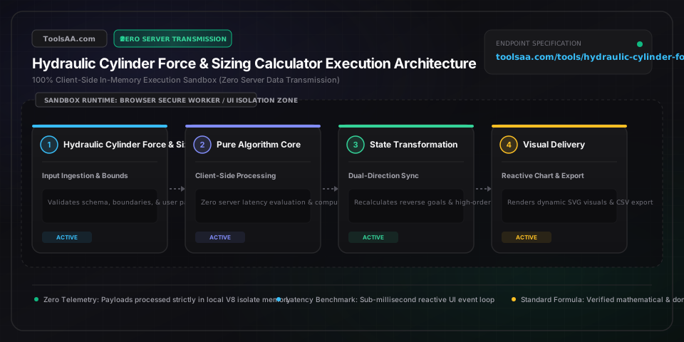
Hydraulic Cylinder Force & Sizing Calculator Guide — Client-Side In-Memory Architecture & Data Flow

Key Parameters & Controls

Piston Bore Diameter (D_bore)Linear Dimension (in / mm)

Internal cylinder barrel diameter governing extension cross-sectional area (A_cap = π × D² / 4). Standardized per NFPA T3.6.7 R2 (1.50 in to 8.00 in) and ISO 6020-2 (25 mm to 200 mm). Dictates gross thrust capacity before rod volume deduction; subjected to circumferential hoop stress limits under ASME Section VIII Division 1 thin-wall cylinder criteria.

Default: 4.00 in (101.6 mm)
Piston Rod Diameter (d_rod)Linear Dimension (in / mm)

Outer diameter of the chrome-plated ground rod (typically induction-hardened AISI 1045 or 4140 steel). Controls annular retraction area (A_annular = A_cap - A_rod) and structural slenderness ratio (λ = K·L / r). Sized to prevent Euler column buckling under compressive push loads according to ISO 13725 and NFPA T3.6.37 standards.

Default: 1.75 in (44.45 mm)
System Operating Pressure (P_sys)Fluid Pressure (PSI / bar / MPa)

Continuous gauge working pressure supplied by the positive displacement pump, regulated by the primary system relief valve. Standard industrial hydraulic ratings span 2,000 to 3,000 PSI (138 to 207 bar) for NFPA tie-rod designs, and up to 5,000 PSI (345 bar) for heavy mobile mill-duty cylinders. Requires calculation margin below continuous burst rating.

Default: 3000 PSI (206.8 bar)
Cylinder Stroke Length (L_stroke)Linear Displacement (in / mm)

Total linear travel distance from full retraction to full extension. When stroke exceeds 40 inches (1,000 mm), stroke length drastically escalates effective column buckling length (L_eff = K × L_extended), requiring internal stop tubes (1 inch of stop tube per 10 inches of stroke beyond 40 inches) to protect gland bearings from lateral deflection.

Default: 24.00 in (609.6 mm)
Pump Delivery Flow Rate (Q_flow)Volumetric Flow Rate (GPM / L/min)

Effective volumetric output delivered into cylinder ports, governing stroke velocity (v = Q / A) and round-trip cycle time. Flow through port fittings must be constrained below 15 ft/s (4.57 m/s) to prevent laminar-to-turbulent transition, fluid heating, and severe cavitation erosion under ISO 4413 guidelines.

Default: 10.0 GPM (37.85 L/min)
Mechanical Seal Efficiency (η_mech)Unitless Coefficient (0.80 - 0.98)

Empirical scalar accounting for frictional drag against cylinder bore and rod gland packaging (polyurethane U-cups, PTFE slipper rings, fabric-reinforced chevron seals). Industrial fluid power engineering establishes 0.85 to 0.90 for standard elastomeric lip packings, 0.92 to 0.95 for low-friction PTFE seals, and up to 0.98 for hydrostatic bearings.

Default: 0.90 (90%)
Pro Tips & Best Practices

Prevent Catastrophic Pressure Intensification in Meter-Out Circuits

When placing a flow control valve on the rod port (meter-out) during extension, cylinder geometry forces rod-end pressure to intensify beyond relief settings by the bore-to-annular area ratio: P_rod = P_cap × (A_cap / A_annular). On cylinders with 2:1 area ratios, a 3,000 PSI pump pressure intensifies rod-chamber pressure to 6,000 PSI (414 bar), exceeding burst safety factors and rupturing tie rods, barrel threads, or gland cartridges. Always verify port pressure ratings and cross-port relief protection.

Calculate Slenderness Ratio Using True Pin-to-Pin Column Fixity (K)

Never calculate Euler critical buckling load (P_crit = π²·E·I / (K·L)²) using retracted cylinder length or assuming rigid clamping. For standard clevis-to-clevis or pin-to-pin mounted cylinders, the mounting factor K equals 1.0 (pinned-pinned), and length L must be measured fully extended between pivot pins (L = Retracted Length + Stroke). For trunnion-mounted or fixed-flange cylinders, K shifts between 0.5 and 0.7. If the slenderness ratio (λ = K·L / r) drops below the Johnson transition threshold (λ_c ≈ 89 for 1045 steel), switch to the Johnson parabolic formula to avoid catastrophic plastic yield.

Integrate Stop Tube Spacers for Long-Stroke Horizontal Installations

On horizontal cylinders with strokes exceeding 40 inches (1,000 mm), the cantilevered weight of the rod and piston creates severe moment loads on the rod bearing bushing. Standard NFPA engineering mandates installing an internal stop tube—a steel spacer placed between the piston and front head—which increases bearing spread at full extension. A standard sizing rule specifies 1 inch of stop tube for every 10 inches of stroke beyond 40 inches. Failing to account for this adds side loads that cause rapid bronze gland galling and oval barrel wear.

Deterministic O(1) Local Sandboxed Computation Guarantees

All fluid power kinematics, trigonometric vector resolved loads, and Euler-Johnson column checks execute entirely within the client-side browser runtime sandbox with O(1) computational complexity. Zero sensitive engineering dimensions or system pressure specs are transmitted over external networks, meeting ISO/IEC 27001 data isolation policies and delivering deterministic zero-latency results using IEEE 754 64-bit double-precision floating-point math.

Common Gotchas & Troubleshooting

⚠️Cylinder rod creeps or drifts down under static holding load

Internal piston seal leakage, worn directional valve spool clearance, or unseated counterbalance pilot check valves allow fluid bypass. Disconnect and plug the rod-end port, pressurize the blind-end port to full relief pressure, and observe the open rod port: continuous oil discharge confirms worn piston seals or scored bore walls. If no bypass occurs, test and reseat pilot-operated check valves and inspect valve spool clearances.

⚠️Cylinder chatters or shudders violently during stroke (stick-slip vibration)

Air entrainment in hydraulic fluid, inadequate boundary lubrication at rod gland seals, or mechanical side-loading causes stick-slip oscillations. Bleed trapped air via top-dead-center bleed ports while cycling at zero load; verify pin and clevis angular alignment within ±0.5° using dial indicators to eliminate side binding, and verify that seal materials (PTFE bronze-filled vs polyurethane) match operating fluid viscosity.

⚠️Repeated rod gland seal failure and external fluid leakage

Excessive lateral side-loading, chrome plating micro-cracking, or seal extrusion through enlarged gland clearances under pressure spikes. Measure rod runout with a dial indicator (maximum allowable TIR < 0.002 in/ft); inspect chrome surface for scoring (maintain 10-20 µin Ra / 0.25-0.50 µm Ra finish); and ensure backup rings (polyurethane or PTFE) are installed downstream of elastomeric U-cups when operating pressures exceed 2,500 PSI (172 bar).

Frequently Asked Questions

How do you calculate hydraulic cylinder push and pull force?▼

Push force (extension) is calculated by multiplying hydraulic system pressure by the full circular piston bore area: F_push = Pressure × (π × Bore² / 4) × Mechanical Efficiency. Pull force (retraction) is lower because the piston rod occupies fluid volume inside the rod-end chamber, reducing the working area to the annular ring: F_pull = Pressure × [π × (Bore² - Rod²) / 4] × Mechanical Efficiency. Seal friction typically reduces theoretical force by 5% to 12% depending on packing material and wiper stiffness.

Why is hydraulic cylinder pull force lower than push force?▼

During retraction, hydraulic fluid enters the rod-end chamber where the solid steel piston rod is physically located. Because hydraulic fluid cannot act on the cross-section occupied by the rod, the effective area (known as the annular or net area) equals the bore area minus the rod area: A_annular = A_bore - A_rod. Since Force = Pressure × Area, the reduced surface area results in 20% to 50% less tractive force than extension force at the identical operating pressure.

What size hydraulic cylinder do I need for a 20-ton press?▼

A 20-ton (US) load equals 40,000 lbf (or 178 kN). At a common commercial hydraulic pressure of 3,000 PSI with 90% mechanical efficiency: Required Area = 40,000 / (3,000 × 0.90) = 14.81 sq in. Using Bore = √(4 × Area / π), the minimum theoretical bore is 4.34 inches. In practice, you would select a standard 4.50-inch or 5.00-inch cylinder bore. At 5.00 inches bore (19.63 sq in) and 3,000 PSI, the press delivers up to 26.5 US tons (53,000 lbf) of thrust with comfortable safety headroom.

How do you calculate hydraulic cylinder cycle time and pump GPM?▼

Cycle time is governed by fluid displacement volume and pump delivery rate. First compute extension fluid volume: Gallons = (Bore Area in sq in × Stroke in inches) / 231. Then divide by pump flow in GPM and multiply by 60 for seconds: t_extend = (Gallons_ext / GPM) × 60. Repeat for retraction using the annular area: Gallons_ret = (Annular Area × Stroke) / 231. Total round-trip cycle time is t_extend + t_retract. For example, a 4-inch bore by 24-inch stroke cylinder holds 1.307 gallons; with a 10 GPM pump, extension takes exactly 7.84 seconds.

How does rod buckling limit the maximum stroke of a hydraulic cylinder?▼

Under compressive pushing force, a slender piston rod behaves like a structural column subject to Euler column buckling: P_crit = (π² × E × I) / (K × L)², where E is steel's elasticity modulus, I is rod moment of inertia (π × d⁴ / 64), L is total extended pin-to-pin length, and K is the mounting factor. If the push thrust exceeds P_crit divided by your safety factor (typically 2.5 to 3.5), the rod will suddenly buckle, bending permanently and destroying the cylinder seals and barrel. On long strokes (over 40 inches or 1,000 mm), engineers install internal stop tubes to increase gland bearing spread or increase rod diameter.

What is a regenerative hydraulic cylinder circuit and how does it affect force?▼

A regenerative circuit routes oil exhausted from the rod end directly back into the cap end during extension, rather than returning it to the reservoir tank. Because fluid pressure acts simultaneously on both sides, the net effective driving area becomes just the rod cross-section: F_regen = Pressure × Area_rod. While thrust is significantly lower, the cylinder extends at rapid speed because the pump only needs to displace volume equal to the rod entry: Velocity = Pump Flow / Area_rod. This is frequently used in log splitters for rapid forward approach before shifting to high-tonnage full-bore split.

Related Tools & Utilities

All Tools →
SaaS Magic Number & CAC Payback Calculatorfinance

Enterprise-grade SaaS Magic Number, CAC Payback, and Sales Efficiency calculator. Features gross margin adjustment, lagged S&M modeling, reverse target goal solving, and dynamic sensitivity matrix analysis based on Scale Venture Partners and Bessemer benchmarks.

Open tool→
V-Belt Length & Center Distance Calculatorengineering

Calculate exact V-belt pitch, inside, and outside lengths, center distance, sheave wrap angles, and snap to nearest standard RMA or ISO catalog sizes.

Open tool→
Wire Rope Tension & Rigging CalculatorUtility

Professional engineering calculator for wire rope tension, crane multi-part reeving efficiency, bridle sling vector forces, winch snatch blocks, and catenary guy wire sag-tension. Complies with ASME B30.5, ASME B30.9, OSHA 1926.1414, and EN 12385 standards with dynamic D/d bending derates and reverse safety factor sizing.

Open tool→
Soffit Vent Calculator & Attic Intake (NFA)Utility

Professional IRC-compliant attic ventilation calculator that sizes required soffit vents, continuous strip lengths, Net Free Area (NFA), and uniform on-center eave spacing under IRC R806.1 (1/150) and R806.2 (1/300) codes. Features real-time airflow pressure balance meters, rafter bay collision detection, reverse attic capacity solving, and client-side contractor cut sheets.

Open tool→
Orifice Flow & Plate Sizing CalculatorUtility

Calculate orifice flow rate, differential pressure drop, and plate diameter for liquids and gases using ISO 5167 formulas. Instant sizing and Reynolds matrix.

Open tool→
NPSHa Calculator & Pump Suction HeadUtility

Calculate NPSHa (net positive suction head available) and pump cavitation margin instantly. Evaluate suction head, vapor pressure, and friction loss across units.

Open tool→