Wire Size & Ampacity Calculator (AWG)
Badge standard100% Client-Side Privacy

Wire Size & Ampacity Calculator (AWG)

Calculate wire size and ampacity instantly. Size copper and aluminum AWG conductors with NEC tables, calculate voltage drop, and apply conduit derating.

Lbl quick presets

Parameters & Inputs

Unit amps
1A
250A+
Lbl continuous multiplier
Unit feet
5ft
300ft+
Lbl advanced variables
Lbl recommended wire
8 AWG
8.37 mm² · Cu
Lbl allowable 50A
Lbl breaker size
50 A
Lbl standard ocpd
Lbl design current prefix 50.0A
Lbl ground wire
10 AWG
Lbl table250
Lbl equipment ground
Lbl voltage drop
1.49%
- 3.56 V
Lbl terminal voltage prefix 236.4V
Lbl conduit size
3/4"
Lbl emt pvc fill
3 Unit conductors

Title cross section svg

Lbl thermal caution zone
8
Lbl conductor core0.1285" (3.26 mm)
Lbl jacket insulation16,510 cmil
Lbl thermal loading80% of Rating
Lbl loop resistance0.0891 Ω
Lbl nec coordination8 AWG copper rated for 50A safe continuous flow under 86° ambient raceway conditions.

Title voltage gradient svg

60 Unit feet Lbl run suffix
Svg panel240VSvg load236.4VLbl midpoint prefix 30 Unit feet- 3.56V (1.49% Lbl drop word) · 135W Lbl loss word
Lbl source potentialLbl delivered voltage prefix 98.51% Lbl of source voltageLbl target limit prefix 3.0% Lbl limit suffix

Title compliance checklist

Badge continuous pass40A × 1.25 = 50.0A Desc design current verified
Badge terminal passDesc terminal cap applied 75°C Desc termination baseline (50A).
Badge conduit passDesc min trade size prefix 3/4" EMT Desc for bundled prefix 3 Unit conductors.
Badge ground pass10 AWG Desc ground wire for breaker 50A Desc breaker rating
Primary Metric
0.0 A
Desc safety margin
Efficiency / Capacity
98.51 %
236.4V Desc delivered at target load
Net Output
89.1 mΩ
Desc loop impedance
Client-Side Processing

High-performance calculation executed entirely in browser memory.

Zero Server Upload Privacy

All payloads remain strictly local with zero external server communication.

Production Ready Export

Clean, optimized output formats ready for immediate deployment.

Legal disclaimer
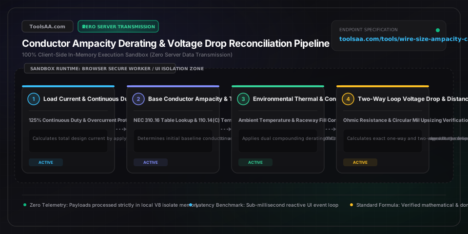
Technical Reference & Architecture Guide

Wire Size & Ampacity Calculator (AWG) Guide

Calculate wire size and ampacity instantly. Size copper and aluminum AWG conductors with NEC tables, calculate voltage drop, and apply conduit derating.

Wire Size & Ampacity Calculator (AWG) Guide — Client-Side In-Memory Architecture & Data Flow

Key Parameters & Controls

loadCurrentAmperes (A)

Operating electrical current drawn by connected equipment; continuous loads running 3+ hours require a mandatory 125% design safety multiplier per NEC 210.19.

Default: 40.0 A
systemVoltageVolts (V)

Nominal electrical system potential (120V standard branch, 240V residential split-phase, 208V commercial line-to-line, 480V industrial three-phase, or 230V/400V IEC).

Default: 240 V
circuitLengthDistance (ft / m)

One-way physical conductor distance from distribution panel overcurrent protection device to the load terminals, dictating cumulative circuit loop resistance.

Default: 60 ft
conductorMaterialMetallurgy (Copper / Aluminum)

Conductor core composition: Electrolytic Annealed Copper (100% IACS conductivity) vs 8000-Series Aluminum Alloy (~61% IACS, requiring approximately two trade sizes larger).

Default: Copper
insulationRatingTemperature (°C)

Thermal endurance threshold of conductor jacket insulation under NEC Table 310.16 (60°C TW/UF, 75°C THWN, or 90°C THHN/XHHW-2).

Default: 90°C (THHN)
terminalRatingTemperature (°C)

Equipment termination temperature ceiling under NEC 110.14(C); standard residential breakers ≤100A clamp usable ampacity to 60°C or 75°C regardless of 90°C wire insulation.

Default: 75°C
ambientTemperatureTemperature (°F / °C)

Peak ambient air temperature surrounding raceway or cable; temperatures above 30°C (86°F) trigger mandatory thermal derating factors per NEC Table 310.15(B)(1).

Default: 86°F (30°C)
conduitConductorCountConductor Count (Bundle)

Total number of current-carrying conductors installed inside a shared raceway or cable; bundles of 4 or more trigger mutual heating derating per NEC Table 310.15(C)(1).

Default: 3 conductors
maxAllowedVoltageDropPercentage (%)

Maximum permissible voltage attenuation across circuit run; NEC 210.19(A) Informational Note No. 4 recommends ≤3% for branch circuits and ≤5% total feeder plus branch.

Default: 3.0%

Pro Tips & Best Practices

The Terminal Temperature Coordination Trap (NEC 110.14(C))

Even when pulling 90°C rated THHN wire, you cannot size the circuit based on the 90°C ampacity column if the circuit breaker or load lugs are only rated for 60°C or 75°C. Under NEC 110.14(C), terminations for circuits 100A or less (or using #14 through #1 AWG) default to the 60°C column unless explicitly stamped '75°C' or 'AL7CU'. However, an insider advantage exists: you are legally permitted to use the higher 90°C rating as the starting calculation point for ambient temperature and conduit bundling derating factors, provided the final derated ampacity does not exceed the equipment terminal rating.

Mandatory 125% Continuous Duty Sizing for EV Chargers and Water Heaters

Under NEC 210.19(A) and 625.41, any load expected to run continuously for 3 hours or longer (such as Level 2 EV charging stations, electric water heaters, space heating, and commercial lighting) must be treated as a continuous load. The branch circuit conductors and overcurrent protective device (breaker) must be sized for at least 125% of the continuous load current. For example, a 48-amp hardwired EV charger draws 48A continuously, requiring a minimum 60-amp circuit breaker (48A × 1.25 = 60A) and minimum #6 AWG copper conductors rated for 65A at 75°C.

Proportional Ground Wire Upsizing Rule (NEC 250.122(B))

When you upsize ungrounded phase conductors to compensate for voltage drop on long runs (for example, stepping up from #10 AWG to #6 AWG for a 150-foot run), NEC 250.122(B) mandates that the equipment grounding conductor (EGC) must also be proportionally increased in circular mil area. Failing to upsize the ground wire when increasing hot conductors is one of the most common reasons electrical installations fail municipal permit inspections, as it compromises the low-impedance ground-fault return path required to trip the breaker instantly during a short.

Rooftop Solar and Attic Temperature Correction Factor Disasters

Attics and rooftop solar conduits regularly experience ambient temperatures between 120°F and 140°F (49°C to 60°C) during peak summer irradiance. Under NEC Table 310.15(B)(1), 90°C THHN copper in a 130°F attic incurs a 0.76 temperature correction factor. If you also run 4 to 6 current-carrying conductors in the same raceway, an additional 0.80 conduit bundling factor compounds the derating (0.76 × 0.80 = 0.608 net multiplier). A #10 AWG copper wire rated 40A at 90°C is derated down to just 24.3A, making it illegal on a 30A breaker and necessitating upsizing to #8 AWG.

AC Effective Impedance vs DC Resistance for Large Commercial Feeders

For small branch circuits (#14 to #4 AWG), calculating voltage drop using DC resistance formula (2 × K × I × L / CM) is sufficiently accurate. However, for large feeders (1/0 AWG and above) carrying alternating current in metallic conduit, AC magnetic inductive reactance (XL) and skin effect become substantial factors. Under NEC Chapter 9 Table 9, effective impedance is calculated as Z_eff = R × cos(theta) + X_L × sin(theta). Steel conduit increases reactance by 15% to 25% compared to PVC, requiring engineers to use exact AC impedance matrices for high-amperage commercial services.

Common Gotchas & Troubleshooting

⚠️Wire gauge satisfies thermal ampacity but causes noticeable light flickering and equipment underperformance.

Thermal ampacity only prevents insulation fire hazard; it does not protect against excessive voltage drop over long conductor runs. On runs exceeding 75 to 100 feet, calculate circuit loop resistance using R = (2 × K × L) / CM. If voltage drop exceeds 3.0%, upsize the conductor by one or two standard trade sizes (e.g. increase #12 AWG to #10 or #8 AWG) to restore terminal voltage and eliminate brownouts.

⚠️Circuit breaker trips nuisance false alarms after 30 to 45 minutes of continuous high-power operation.

This is the classic symptom of violating the 80% continuous load rule (NEC 210.20). Standard thermal-magnetic circuit breakers are calibrated to carry 100% of their rating intermittently, but will trip thermally when loaded above 80% for more than 3 hours due to internal bimetallic strip heat accumulation. Verify that continuous loads do not exceed 80% of breaker rating (e.g. max 16A on a 20A breaker, max 40A on a 50A breaker).

⚠️Aluminum wire terminations show signs of oxidation, overheating, or insulation melting at the breaker terminal.

Aluminum expands and contracts at a significantly higher thermal coefficient than copper, leading to terminal loosening and resistive hot spots if improperly installed. Ensure that all breakers and terminal blocks are explicitly dual-rated and stamped 'AL7CU' or 'CO/ALR'. Wire ends must be wire-brushed, coated with approved anti-oxidant joint compound (such as Penetrox or Noalox), and torqued to exact manufacturer specifications in inch-pounds using a calibrated torque tool per NEC 110.14(D).

⚠️Multiple branch circuits bundled through the same conduit hole fail code inspection.

Passing more than three current-carrying conductors through a single raceway, sleeve, or framing penetrations fire-caulked together triggers NEC Table 310.15(C)(1) bundling penalties (4 to 6 conductors derate to 80%; 7 to 9 derate to 70%). For multi-wire installations, separate conductors into multiple conduit runs or upsize conductor gauge so the derated ampacity still equals or exceeds the overcurrent breaker rating.

Frequently Asked Questions

How do you calculate wire size and ampacity for an electrical circuit?▼

To calculate wire size and ampacity, establish design current by taking 100% of non-continuous loads plus 125% of continuous loads (operating 3+ hours) per NEC 210.19. Next, consult NEC Table 310.16 for base ampacity based on conductor metallurgy (copper or aluminum) and insulation rating (60°C, 75°C, or 90°C), clamped to equipment terminal ratings per NEC 110.14(C). Then apply ambient temperature correction factors (Table 310.15(B)(1)) and conduit bundling adjustment factors (Table 310.15(C)(1)). Finally, verify that circuit distance does not cause voltage drop to exceed 3% using Ohm's law: Voltage Drop = (2 × K × I × Length) / Circular Mils, upsizing the wire gauge if necessary.

What wire size do I need for a 50 amp breaker circuit?▼

For a standard 50-amp circuit breaker, the National Electrical Code requires #6 AWG copper wire or #4 AWG aluminum wire under standard 75°C terminal ratings. At 75°C, #6 AWG copper carries up to 65 amps and #4 AWG aluminum carries up to 65 amps, safely exceeding the 50A breaker rating. While #8 AWG 90°C copper has a base table rating of 55A, NEC 110.14(C) terminal rules restrict circuits 100A and under to 75°C (where #8 AWG is rated only 50A, leaving zero headroom). Therefore, #6 AWG copper is the universal standard for residential 50A EV chargers and electric ranges.

How does copper wire ampacity compare to aluminum wire?▼

Copper possesses roughly 61% higher electrical conductivity than aluminum per unit of cross-sectional area, meaning aluminum conductors have higher electrical resistance and generate more resistive heat for an identical wire thickness. Consequently, aluminum wire must be approximately two AWG gauge sizes larger than copper to carry equivalent current (for example, #2 AWG copper and 1/0 AWG aluminum both provide 115A to 120A allowable ampacity at 75°C). Aluminum is significantly lighter and approximately 50% to 70% cheaper for heavy service feeders (100A to 200A), but requires dual-rated AL7CU terminals, anti-oxidant paste, and precise torque setting.

How far can you run electrical wire before voltage drop requires upsizing?▼

As a standard engineering guideline under the National Electrical Code, voltage drop typically exceeds the recommended 3% threshold at approximately 100 feet (30.5 meters) for standard 120V circuits operating near 80% capacity. For example, a 120V 15-amp load on standard #14 AWG copper wire incurs a 3.6% voltage drop (4.32V lost) at 100 feet; upsizing to #12 AWG copper reduces the drop to 2.3% (2.76V lost), bringing the circuit safely back within code compliance. For 240V circuits, the allowable distance before exceeding 3% doubles to approximately 200 feet.

How does the NEC 80% continuous load rule change required wire gauge?▼

Under NEC Sections 210.19(A), 210.20, and 215.2, an electrical branch circuit must not be loaded beyond 80% of its overcurrent protective device (breaker) capacity if the connected load runs continuously for 3 hours or more. Equivalently, the circuit breaker and conductor ampacity must be sized to at least 125% of the continuous load current. For example, a continuous 16-amp load (such as a 3.8 kW Level 2 EV charger) requires a minimum 20-amp breaker (16A × 1.25 = 20A) and #12 AWG copper wire, while a 40-amp continuous load requires a 50-amp breaker and #6 AWG wire.

Can you use the 90°C wire ampacity column with standard 75°C circuit breakers?▼

No, you cannot use the 90°C ampacity column for final circuit sizing unless every component in the circuit—including the circuit breaker, disconnect switch, and appliance lugs—is explicitly rated and listed for 90°C operation. Standard residential and commercial circuit breakers are rated for 60°C or 75°C terminations. Under NEC 110.14(C), the maximum allowable continuous current cannot exceed the ampacity rating at the lowest-rated terminal temperature (typically 75°C). However, you ARE legally permitted to use the higher 90°C column as the starting baseline when calculating ambient temperature and conduit bundling derating factors.

Related Tools & Utilities

All Tools →