Short title

Conduit Cable Pulling & SWBP Calculator

Calculate cable pulling tension, conduit sidewall bearing pressure (SWBP), and jamming ratio across multi-bend runs with instant forward vs reverse solver.

Badge zero serverBadge nec compliant
Presets

Section raceway params

Section route builder

1Lbl type straight
2Lbl type bend
3Lbl type straight
4Lbl type bend
5Lbl type straight
6Lbl type bend
7Lbl type straight

Section quick tweaks

Lbl friction sensitivity0.200 μ (1.0x)

Desc friction sensitivity

Lbl tail tension25 Unit lbs
10 lbs (Free Reel)60 lbs (Braked)120 lbs (Heavy Drag)
Kpi max tension
267.2Unit lbs
Kpi allowable tension: 12,000
Kpi max s w b p
46.3Unit lbs per ft
Lbl cap: 500 lbs/ft
Kpi safety margin
97.8%
Status safe
Kpi recommended direction
B → A
Badge reverse pull

Tab tension profile — Lbl heatmap

Lbl end aLbl end bLbl max limit: 12,000 Unit lbs#1#216#3#441#5#646#7
Hint click node

Tab tension profile — Lbl table

Col segment indexCol typeCol detailsCol in tensionCol out tensionCol s w b pCol status
#1Lbl type straight40 Unit ft (Dir horizontal)25 Unit lbs40.6 Unit lbs—Status safe
#2Lbl type bend90° (24 Unit inches R)40.6 Unit lbs59.2 Unit lbs15.8 Unit lbs per ftStatus safe
#3Lbl type straight120 Unit ft (Dir horizontal)59.2 Unit lbs105.9 Unit lbs—Status safe
#4Lbl type bend90° (24 Unit inches R)105.9 Unit lbs154.5 Unit lbs41.3 Unit lbs per ftStatus safe
#5Lbl type straight60 Unit ft (Dir horizontal)154.5 Unit lbs177.9 Unit lbs—Status safe
#6Lbl type bend90° (36 Unit inches R)177.9 Unit lbs259.5 Unit lbs46.3 Unit lbs per ftStatus safe
#7Lbl type straight20 Unit ft (Dir horizontal)259.5 Unit lbs267.2 Unit lbs—Status safe

Engineering disclaimer

Kpi max tension267.2 Unit lbs
Kpi allowable tension12,000 Unit lbs
Kpi max s w b p46.3 Unit lbs per ft
Kpi conduit fill23.5%
Kpi jamming ratio3.57
Kpi recommended directionB → A
Technical Reference & Architecture Guide

Conduit Cable Pulling & SWBP Calculator Guide

Calculate cable pulling tension, conduit sidewall bearing pressure (SWBP), and jamming ratio across multi-bend runs with instant forward vs reverse solver.

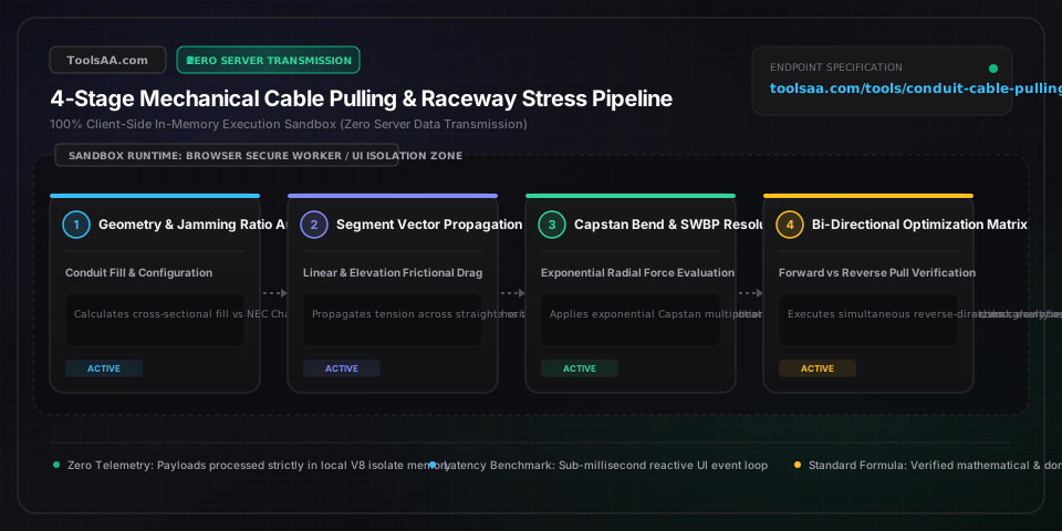
Conduit Cable Pulling & SWBP Calculator Guide — Client-Side In-Memory Architecture & Data Flow

Key Parameters & Controls

Conductor Circular Mil Area & Pulling Eye Tensile LimitEngineering Cross-Section Area

Cross-sectional conductor area (kcmil / AWG / mm2). Governs maximum safe mechanical pulling force without elongating or necking the metal core. Safe threshold standard: 0.008 lb per circular mil (70 N/mm2) for annealed copper; 0.006 lb per circular mil (42 N/mm2) for AA-8000 aluminum.

Default: 500 kcmil (500,000 cmil)
Weight Correction Factor (w_c)Conductor Geometry Multiplier

Dimensionless coefficient accounting for mutual wedging and lateral pinching between multiple conductors in a circular raceway. Equals 1.0 for single cables; calculated dynamically for 3 conductors in cradle configuration as 1 + (4/3)*(d/(D-d))^2, or triangular configuration as 1 / sqrt(1 - (d/(D-d))^2).

Default: 1.18 to 1.35
Sidewall Bearing Pressure (SWBP / SP)Radial Force Per Linear Bend Length

Radial crushing force exerted on the cable insulation and jacket against the inner raceway curve during tensioned bends. Calculated as T_out / R (single cable) or T_out*(3*w_c - 2)/(3*R) (three cables). IEEE 525 safe benchmark limits: 500 lbs/ft (7.3 kN/m) for standard 600V power cables, 1,000 lbs/ft (14.6 kN/m) for shielded MV/HV cables, and 300 lbs/ft (4.4 kN/m) for fiber optic cables.

Default: Max 500 lbs/ft
Cable Jamming Ratio (D / d)Clearance Dimension Ratio

Ratio of conduit inside diameter (D) to single cable outside diameter (d). When pulling 3 cables, if D/d falls between 2.8 and 3.2, cables can slip from a triangular into a flat side-by-side alignment in bends, wedging solidly against raceway walls and causing catastrophic lockup.

Default: Outside 2.8 - 3.2
Dynamic Coefficient of Friction (mu)Surface Interface Friction Factor

Kinetic friction multiplier between the cable jacket (PVC, XLPE, HDPE) and raceway wall (EMT, RMC, PVC). Benchmarks: 0.15 to 0.20 for high-grade synthetic polymer pulling lubricant; 0.35 for standard soap/wax lube; 0.50 or higher for unlubricated dry pulls.

Default: 0.20 (Lubricated)
NEC Conduit Fill PercentageRaceway Space Capacity Ratio

Ratio of total conductor cross-sectional area to internal raceway area. Regulated under National Electrical Code (NEC) Chapter 9, Table 1: maximum 53% for 1 conductor, 31% for 2 conductors, and 40% for 3 or more conductors.

Default: Max 40.0%
Pro Tips & Best Practices

Always Pull Toward the End Closest to the Bends

Because bends multiply tension exponentially by e^(mu * theta * w_c), entering a bend with already high straight-run tension causes explosive tension and SWBP spikes. Pulling toward the end nearest the bends keeps entry tension (T_in) near zero, frequently cutting peak pulling force by 50% to 70%.

Standard Factory Elbows Are the #1 Cause of SWBP Cable Failure

A standard 3-inch factory conduit 90-degree elbow has a tight centerline radius of only 15 inches (1.25 ft). If tension entering or exiting that bend reaches 2,000 lbs, SWBP hits 1,600 lbs/ft—crushing 600V insulation. Upgrading to a 36-inch or 48-inch field sweep immediately drops SWBP below the 500 lbs/ft threshold.

Basket Pulling Grips Cut Allowable Tension to 1,000 lbs

When pulling with a woven mesh basket grip over the cable jacket instead of crimped pulling eyes bolted directly to the copper/aluminum conductors, the maximum allowable pulling force drops to 1,000 lbs (or manufacturer rating), regardless of conductor size, to prevent jacket shearing.

Downward Vertical Pulls Can Lock Bends Due to Weight Vectoring

Pulling cable down a vertical riser into a horizontal run creates negative gravitational tension at the top, but if back-tension is not applied to the reel, cable free-fall bunches up into the lower elbow, drastically increasing the effective coefficient of friction and causing mechanical wedging.

Common Gotchas & Troubleshooting

⚠️Sidewall bearing pressure (SWBP) exceeds the 500 lbs/ft insulation damage threshold

First, test reversing the pull direction in the calculator; if bends are closer to the payout reel, tension drops exponentially. Second, replace standard short-radius elbows with 36-inch or 48-inch large radius sweeps. Third, upgrade pulling lubricant to reduce friction coefficient from 0.35 to 0.18.

⚠️Total pulling tension exceeds conductor tensile limit (0.008 lb/cmil for Cu or 0.006 lb/cmil for Al)

Split the raceway into two pulls by introducing an intermediate pull box or manhole. If raceway geometry cannot be altered, switch from a single-end puller to a synchronized mid-point capstan assist, or increase conductor cross-section to raise tensile capacity.

⚠️Conduit-to-cable diameter ratio falls squarely inside the 2.8 to 3.2 jamming hazard zone

Upsize the conduit by one trade size to increase D/d above 3.2, ensuring conductors naturally maintain a stable triangular cross-section through curved sweeps without rolling into a jammed flat profile.

⚠️Conduit fill exceeds the NEC 40% maximum allowable limit for 3+ conductors

Upsize conduit diameter or split conductors into parallel runs across two separate raceways under NEC 310.10(G). Parallel raceways lower individual pull tension and provide thermal ampacity relief under NEC 310.15(C)(1).

Frequently Asked Questions

How do you calculate cable pulling tension in a conduit?▼

Cable pulling tension is calculated segment-by-segment using two fundamental equations. For straight horizontal sections, tension increases linearly: T_out = T_in + (mu * L * w * w_c), where mu is the friction coefficient, L is length, w is cable linear weight, and w_c is the weight correction factor. For curved conduit bends, tension increases exponentially following the Capstan equation: T_out = T_in * e^(mu * theta * w_c), where theta is the bend angle in radians. The exit tension of each segment becomes the entering tension for the next segment along the run.

What is maximum allowable sidewall bearing pressure (SWBP) for electrical cables?▼

Under IEEE 525 and ICEA industry standards, the maximum allowable sidewall bearing pressure (SWBP) is 500 lbs/ft (7.3 kN/m) for standard 600V XLPE and EPR commercial power cables, 1,000 lbs/ft (14.6 kN/m) for medium-voltage 5kV-35kV shielded power cables, and 300 lbs/ft (4.4 kN/m) for armored fiber optic cables. Exceeding these thresholds permanently deforms the insulation and compromises dielectric breakdown voltage.

How do you determine which direction to pull cable through conduit?▼

Always pull in the direction that positions the majority of conduit bends closest to the cable feed reel (End A) rather than the pulling winch (End B). Because bends multiply entering tension exponentially (T_out = T_in * e^(mu * theta)), entering a bend with low tension from a short run results in a small tension increase, whereas entering a bend after 300 feet of straight run with high tension multiplies that force massively, often doubling total pull tension and crushing cables at the final bend.

What is the cable jamming ratio and how is it calculated?▼

The jamming ratio equals the conduit inside diameter divided by the individual cable outside diameter: J = D / d. Jamming occurs when pulling three identical cables through conduit bends if the ratio falls between 2.8 and 3.2. Within this critical window, the cables twist and can roll from a triangular resting shape into a flat side-by-side configuration across the bend curve, wedging tightly between the raceway walls and locking the pull completely.

Related Tools & Utilities

All Tools →