Short title
Badge standard

Air Receiver Tank Calculator & Sizing

Size compressed air receiver storage tanks in US gallons, liters, and cubic feet using ASME / CAGI drawdown equations, matching air compressor SCFM supply against peak intermittent demand, allowable pressure band (ΔP), and compressor cycle-frequency limits.

Lbl load sample

Lbl calc mode

Lbl delta p = 20 Unit pressure imperial
125

Hint compressor flow

140

Hint peak demand

1.00 Unit time min
Unit pressure imperial
Kpi recommended volume
1,168
Unit volume imperial (156.2 Unit volume cu ft)
ASME-V-1550
Kpi hold up time
448
Unit time sec (7.5 Unit time min)
Lbl buffer status safe
Kpi usable air
216
SCF (ΔP Cushion)
125 → 105 PSI
Lbl recharge pump up time
104
Unit time sec (Recharge cycle)
9 Lbl cycle status normal
Lbl vertical ASME VIII
Lbl vessel drainLbl vessel safety valveLbl vessel air inlet125 Unit flow imperialLbl vessel air outlet140 Unit flow imperialLbl vessel capacity1550 Gal125 PSIØ 54" × 168" H

Title math proof

Lbl step1 formula
V (cu ft) = [ T_min × (C_demand - Q_supply) × P_atm ] / ΔP
Lbl step2 substitution
V = [ 1.00 min × (154.0 - 125 SCFM) × 14.43 psia ] / 20 psi
Lbl step3 result
V = 156.19 Unit volume cu ft × 7.48052 = 1,168 Unit volume imperial (4,421 L)

Title asme table

Desc asme table

Th tank modelTh volume galTh volume litersTh dimensionsTh orientationTh suitability
ASME-V-303011416" × 38"Lbl vertical-
ASME-V-606022720" × 48"Lbl vertical-
ASME-V-808030324" × 48"Lbl vertical-
ASME-V-12012045424" × 68"Lbl vertical-
ASME-H-12012045424" × 68"Lbl horizontal-
ASME-V-20020075730" × 72"Lbl vertical-
ASME-V-24024090830" × 84"Lbl vertical-
ASME-H-24024090830" × 84"Lbl horizontal-
ASME-V-4004001,51436" × 93"Lbl vertical-
ASME-V-5005001,89336" × 115"Lbl vertical-
ASME-V-6606602,49842" × 115"Lbl vertical-
ASME-V-8008003,02848" × 112"Lbl vertical-
ASME-V-10601,0604,01348" × 144"Lbl vertical-
ASME-V-15501,5505,86754" × 168"Lbl verticalBadge best match
ASME-V-20002,0007,57160" × 172"Lbl verticalBadge alternate
ASME-V-25602,5609,69066" × 178"Lbl vertical-
ASME-V-30003,00011,35672" × 182"Lbl vertical-
Stat elasticity title
Stat elasticity value

Stat elasticity desc

Stat moisture title
Stat moisture value

Stat moisture desc

Stat motor wear title
Stat motor wear value

Stat motor wear desc

Client-Side Processing

High-performance calculation executed entirely in browser memory.

Zero Server Upload Privacy

All payloads remain strictly local with zero external server communication.

Production Ready Export

Clean, optimized output formats ready for immediate deployment.
Technical Reference & Architecture Guide

Air Receiver Tank Calculator & Sizing Guide

Size compressed air receiver storage tanks in US gallons, liters, and cubic feet using ASME / CAGI drawdown equations, matching air compressor SCFM supply against peak intermittent demand, allowable pressure band (ΔP), and compressor cycle-frequency limits.

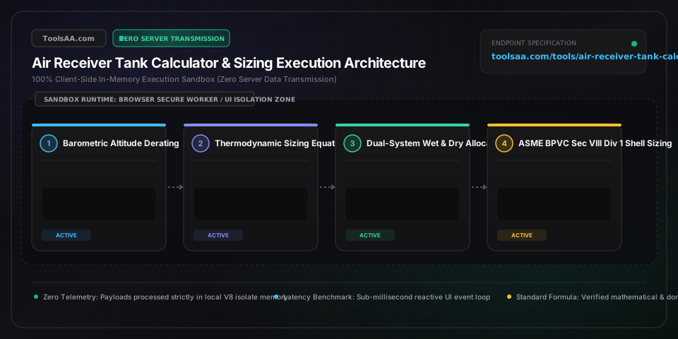
Air Receiver Tank Calculator & Sizing Guide — Client-Side In-Memory Architecture & Data Flow

Key Parameters & Controls

Air Compressor Continuous Delivery Flow (SCFM / FAD)Continuous free air delivery rate

The true volume of compressed air delivered by the pump at full operating discharge pressure under CAGI standards. In standard workshop and commercial setups, 1 electric motor horsepower typically produces 3.5 to 4.5 SCFM at 100 to 125 PSIG.

Default: 25 SCFM
Peak Intermittent Demand Flow Rate (SCFM)Peak tool air consumption rate

The maximum combined airflow consumed by burst pneumatic equipment—such as blast cabinets, paint spray booths, orbital sanders, or heavy impact wrenches—during high-draw cycles that temporarily exceed the compressor supply output.

Default: 45 SCFM
Allowable Operating Pressure Differential (Delta P)Usable pressure differential band

The allowable pressure drop between compressor cut-out pressure (maximum tank pressure) and minimum required tool operating cut-in pressure. Industrial standards benchmark a 15 to 30 PSI differential band to safeguard tool performance while preventing motor short-cycling and saving ~0.5% energy per PSI reduction.

Default: 20 PSI
Peak Demand Duration (Minutes)Drawdown event time window

The continuous elapsed time during which peak tool consumption surpasses compressor pump output. Standard ASME and CAGI sizing equations require dedicated storage buffer volume to bridge this exact deficit window without dropping below critical header pressure.

Default: 1.5 min
Compressor Drive Architecture & Duty ProfilePumping technology classification

The pump mechanical drive type dictating motor thermal cycle limits and pulsation dampening needs: Reciprocating Piston requires 3.0 to 5.0 gal/SCFM for pulsation cushioning; Fixed-Speed Rotary Screw requires 2.0 to 3.0 gal/SCFM to stay under 10 to 12 load cycles/hr (NEMA MG-1); Variable Speed Drive (VSD) requires 1.0 to 1.5 gal/SCFM for speed control stability.

Default: Fixed-Speed Rotary Screw (2.5 gal/SCFM)

Pro Tips & Best Practices

Install the 70/30 Dual-Receiver Wet and Dry Storage Split

Placing 100% of your storage capacity after the dryer causes violent velocity surges during sudden tool draws, overwhelming the refrigerated dryer heat exchanger and spitting liquid moisture downstream into paint guns and sanders. The gold-standard industrial layout splits storage: position a wet receiver (30% to 40% of total volume) directly between the compressor aftercooler and dryer to knock out bulk moisture and oil aerosols, followed by a dry receiver (60% to 70% of volume) post-filtration to buffer demand without disturbing dryer dwell velocity.

Pair Widened Pressure Bands with Downstream Flow Controllers to Avoid the 0.5% Energy Penalty

While widening your pressure band (Delta P) from 15 PSI to 30 PSI doubles usable air storage in the exact same vessel, pumping against higher discharge pressure costs real utility cash—roughly 1% more motor power for every 2 PSI increase (~0.5% per PSI). To harvest maximum storage energy without inflating your electric bill, pump the tank to 125 PSIG but install a high-precision flow-pressure controller at the tank discharge set to a stable 90 PSIG, guaranteeing tools constant regulated pressure while saving pump motor strain.

Prevent Usable Air Loss by Installing Zero-Air-Loss Electronic Drains

A 120-gallon receiver operating in a humid garage or workshop can condense 2 to 4 gallons of water every day. If fitted with a neglected manual drain cock, pooled water silently steals vessel air cushion, causing your compressor to mysteriously start short-cycling after several months. Install a zero-air-loss electronic condensate drain valve with an integrated level sensor: it expels heavy condensate automatically without wasting valuable compressed air volume.

Always Require ASME Section VIII Div 1 & National Board Stamping

Never repurpose obsolete propane tanks, hot water heaters, or uncertified imported steel tanks as compressed air receivers. Compressed air behaves like a loaded mechanical spring; catastrophic shell failure causes severe shockwaves. Legitimate air receivers must carry an engraved ASME Section VIII Division 1 'U' or 'UM' code stamp, a 3.5:1 tensile safety factor rating, 100% hydro-testing to 1.3 times Maximum Allowable Working Pressure (MAWP), and an approved UV safety relief valve.

Common Gotchas & Troubleshooting

⚠️Air compressor is short-cycling rapidly every 30 to 90 seconds, causing motor overheating and contactor chatter

Short-cycling occurs when the buffer volume is too small or flow restriction chokes the tank inlet. First, verify whether your pressure switch sensing line is tapping downstream of high-restriction coalescing filters or narrow whip hoses, which create artificial pressure drop and trick the pressure switch into rapid cycling. If pipe diameter is adequate, calculate tank volume against NEMA MG-1 motor thermal rules: ensure storage capacity equals at least 2.5 to 3.0 gallons per rated SCFM (for fixed-speed screw) or upgrade to an auxiliary secondary receiver manifolded in parallel to lengthen run cycles to a healthy 6–10 minutes.

⚠️Severe pressure drop at point-of-use tools despite tank pressure gauge indicating full cut-out pressure

This symptom points to high dynamic friction drop through undersized outlet plumbing or choked filtration elements rather than an undersized main receiver. Calculate pipe velocity: compressed air distribution headers should never exceed 20 to 30 feet per second (fps). If the main tank sits more than 50 feet away from high-burst tools (like plasma tables, tire bead seaters, or automatic blast cabinets), install a dedicated 30- to 60-gallon point-of-use buffer receiver directly adjacent to the tool with full-port ball valves to satisfy transient impulse airflow locally.

⚠️ASME safety relief valve intermittently pops or weeps air during normal cut-out transitions

Inspect the margin between compressor high-pressure cut-out switch setting and the safety valve setpoint. The ASME pressure relief valve must be rated at or below the tank's certified MAWP, but compressor cut-out should always be calibrated at least 15 to 20 PSI below the safety relief valve rating. If cut-out is properly set at 150 PSI and the relief valve is set to 175 PSI, examine the pressure gauge accuracy (bourdon tubes often drift by 10-15 PSI) or check for unloader valve exhaust failures that trap residual head pressure against the relief seat.

Frequently Asked Questions

How to calculate air receiver tank size for an air compressor?▼

Air receiver tank volume is calculated using the formula V = (t * (C_demand - C_supply) * P_a) / (P_1 - P_2), where V is receiver volume in cubic feet, t is peak duration in minutes, C_demand is tool air consumption in SCFM, C_supply is compressor output in SCFM, P_a is atmospheric pressure (14.7 PSIA at sea level), and (P_1 - P_2) is the permissible pressure differential band in PSI. To convert cubic feet to US gallons, multiply the resulting volume by 7.4805 (or multiply by 28.317 for metric liters). For general buffer installations without specific peak spikes, multiply your compressor rated CFM by 2 to 4 gallons.

What is the rule of thumb for sizing an air receiver tank?▼

The universal engineering rule of thumb is 1.0 to 4.0 US gallons of tank capacity per rated CFM of compressor delivery (or 10 to 30 liters per m³/h). Modern variable speed drive (VSD) compressors need only 1.0 to 1.5 gallons per CFM because the electric motor dynamically matches pump speed to demand. Standard fixed-speed rotary screw compressors require 2.0 to 3.0 gallons per CFM to satisfy NEMA MG-1 limits of 10 to 12 load/unload cycles per hour. Heavy reciprocating piston compressors and pulsating impact setups require 3.0 to 5.0 gallons per CFM to absorb piston shock pulses.

What happens if an air receiver tank is too small?▼

An undersized air receiver causes rapid short-cycling, forcing the motor and intake unloader valves to cycle dozens of times per hour instead of maintaining steady run cycles. This causes three critical failures: first, electric motor windings overheat from repetitive inrush current spikes, violating NEMA thermal start thresholds and burning out stator coils; second, mechanical unloader valves and spin-on oil separators wear out prematurely, causing oil carryover into airlines; third, sudden tool triggers cause instant line pressure collapses, stalling automated CNC pneumatic clamps, degrading paint finishes, and tripping low-pressure safety shutoffs.

What is the difference between wet receiver and dry receiver tanks?▼

A wet air receiver is placed upstream of the air dryer, while a dry air receiver is placed downstream of the air dryer and filtration stages. A wet receiver acts as a bulk thermal and liquid knockout vessel, cooling compressed air and separating 60% to 70% of condensed water and lubricating oil mist before moisture reaches the dryer. A dry receiver stores clean, dry, treated air, acting as an instant pressure buffer for plant equipment without creating high-velocity air rushes through the desiccant or refrigerated dryer that would ruin dew point integrity.

How does pressure band (cut-in vs cut-out) affect air receiver volume?▼

Usable air storage capacity is directly proportional to the differential between compressor cut-out pressure and minimum required system cut-in pressure (Delta P). For example, widening the pressure band from 10 PSI to 30 PSI triples the usable mass of air stored inside the exact same physical vessel, allowing a 120-gallon receiver to provide the equivalent operational buffer of a 360-gallon tank on a tight 10 PSI band. However, every 2 PSI of elevated compressor discharge pressure increases electric motor energy draw by approximately 1% (or ~0.5% per PSI), requiring a deliberate balance between tank size and utility operating costs.

How to size an air receiver for high intermittent peak demand?▼

To size an air receiver for high intermittent peak demand, calculate the volumetric shortfall between peak tool draw and compressor output over time using the drawdown formula: V = (t * Deficit * 14.7) / Delta P. For instance, if a 150 SCFM sandblast cabinet runs for 2 minutes on a 50 SCFM compressor (a 100 SCFM deficit for 2 minutes = 200 standard cubic feet needed) with an allowable pressure drop of 25 PSI (from 120 PSI down to 95 PSI), the required storage volume is V = (2 * 100 * 14.7) / 25 = 117.6 cubic feet, which equals approximately 880 US gallons. This peak demand is best served by installing an 800- to 1,000-gallon ASME surge tank adjacent to the blasting booth.

Related Tools & Utilities

All Tools →
Vector Cross Product Calculator (3D & Area)math

Calculate 3D vector cross product A × B with step-by-step 3×3 determinant expansion, real-time 3D interactive visualizer, unit normal vector, parallelogram area, and orthogonality verification.

Open tool→
Queuing Theory Calculator (Erlang C & M/M/c)math

Industrial-grade queuing theory calculator implementing M/M/1, M/M/c (Erlang C), M/M/c/K (finite buffer), and M/M/c/c (Erlang B loss system) models. Calculate server utilization, delay probability, average wait time (Wq), queue length (Lq), and Service Level Agreement (SLA) percentages. Features automated reverse goal staffing solver, agent shrinkage adjustments, economic cost optimization, dynamic sensitivity matrices, and side-by-side A/B architecture comparison workbench.

Open tool→
Beer Priming Sugar & Carbonation CalculatorUtility

Calculate exact beer priming sugar weights in grams and ounces for dextrose, sucrose, DME, and honey with bottle burst pressure safety and syringe dosing.

Open tool→
Landed Cost & Import Unit Cost Calculatorfinance

Calculate total landed cost and per-unit import cost with duty, ocean freight, customs brokerage, insurance, and harbor fees. Solve target profit margins instantly.

Open tool→
Customs Duty Calculator & Import Tarifffinance

Calculate exact customs duty, import tariff, VAT/GST, and landed cost for US, EU, UK, and CA. Includes FOB vs CIF rules, de minimis limits, and Section 301 fees.

Open tool→
Cap Rate Calculator & Real Estate NOIfinance

Institutional-grade real estate cap rate and NOI valuation calculator for commercial and residential properties. Features itemized pro-forma operating expense ledgers, reverse target acquisition solvers, mortgage debt leverage metrics (Cash-on-Cash, DSCR, break-even occupancy), dynamic 2D price-to-yield sensitivity matrices, and one-click PDF/Excel deal exports.

Open tool→